 |
|
Covington Innovations Home > Astronomy and Astrophotography > Links > Digital SLR Notes > Serial Cable for Canon EOS 40D


Building a Serial-Port Cable for the Canon EOS 40D
Note: Please read my notes on cables for the EOS Digital Rebel and heed the cautions there. Do not connect anything to your camera unless you are sure you have built it correctly and it is safe.
How the EOS 40D is different
Serial- or parallel-port cables for the EOS Digital Rebel system are commonly used by amateur astronomers to give the computer a way to hold the shutter open for a time exposure. They simulate the action of a photographer holding the button on a cable release.
The EOS 40D is different from the Digital Rebels in several ways:
- The cable-release socket is a Canon N3 connector instead of a 2.5-mm phone jack.
- The cable-release socket requires you to close two switch contacts, not just one, to make a time exposure (on "Bulb") successfully.
- If you are controlling the camera by USB port, you do not need to use the cable-release socket at all; "open shutter" and "close shutter" are available as USB commands.
I happen to be controlling my camera with a serial-port cable attached to a homemade microprocessor-based timer, not a PC, so USB is not an alternative. You might also need a serial-port cable for a 40D if you are using older software that does not control this camera by USB.
The Canon N3 connector
Here, reproduced from Digital SLR Astrophotography, is the pinout of the N3 connector on the camera:
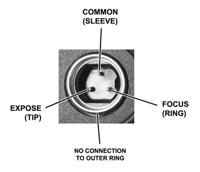
Here "tip," "ring," and "sleeve" refer to the corresponding parts of the phone plugs used on Digital Rebels.
As far as I know, the N3 connector is made only by Canon, and the only way to get one is to hack into a Canon accessory, such as an RS-80N3 cable release. That's what I did.
What's going on inside the camera
The internal circuitry of the 40D is very similar to that of the Digital Rebel cameras and is roughly the following:
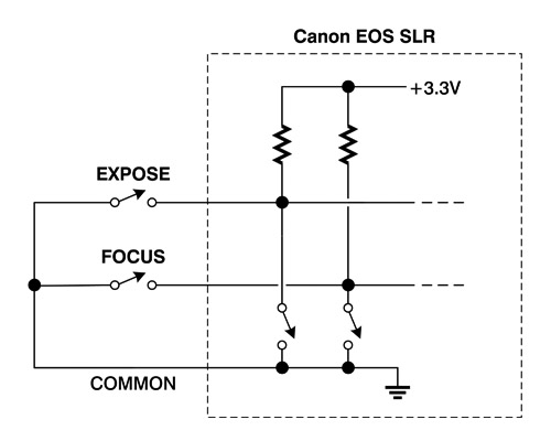
There are "focus" and "expose" switches inside the camera as well as in the RS-80N3 cable release (shown here). When you push the button halfway, "focus" is closed; pushing it the rest of the way closes the "expose" switch also.
Unlike most other EOS cameras, the EOS 40D requires both switches to be closed in order to sustain a time exposure on "Bulb." If you have made a serial-port cable or homemade cable release that only closes one of them (the "expose" switch, sufficient for the Digital Rebels), you'll need to make changes.
Mark Bayley tells me that the above is true only when Mirror Lockup is not enabled. If Mirror Lockup is enabled, a single switch is sufficient. I have not tested this myself.
One excessively simple solution is to tie together the "expose" and "focus" pins of the N3 connector. Then, closing one switch (or one switching transistor) will indeed take a picture, but there is no longer a distinction between pushing the button on the camera halfway and all of the way. Thus you cannot push it halfway down to exit review mode or hide the info display. The two switches actuated by the button are tied together.
Serial-port cables
For a better solution, let's review how a traditional serial-port cable for a Digital Rebel works. It's usually built something like this:
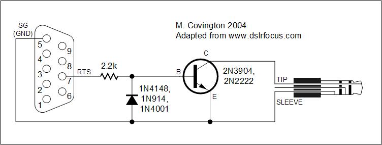
When the computer outputs a positive voltage on pin 5, the transistor conducts and acts like a closed switch. The alternative is a negative voltage which might damage the transistor, so the diode shunts it aside. The resistor limits current.
After pondering several ways to use two transistors, I decided I needed a super-simple circuit that could be built inside a 9-pin plug housing. Instead of NPN bipolar transistors, I decided to use a pair of 2N7000 enhancement-mode MOSFETs. Here's what I came up with:
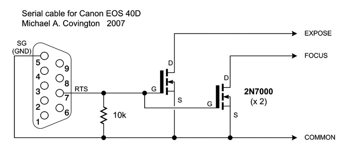
The gate of the 2N7000 can withstand substantial positive or negative voltages, so no diode is needed, and a current-limiting resistor is also not needed. The resistor included here serves a different purpose — to dissipate static electricity on the gate, protecting the 2N7000s from damage and preventing erratic behavior when no source of input is connected.
The whole thing fits neatly into a plug housing; here's what it looks like:
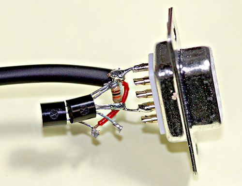
This is not as flimsy as it looks because the cable shield (connected to "common") is soldered directly to Pin 5 of the plug; thus tugging on the cable will not pull the parts apart. I considered gluing the two 2N7000's together to make something like a 6-pin integrated circuit.
Copyright 2007 Michael A. Covington. Caching in search engines is explicitly permitted. Please link to this page rather than reproducing copies of it. This page is not in any way connected with or endorsed by any photographic manufacturer. Many of the product names that appear on this page are registered trademarks of their respective owners.