|
|
|
2019
September
30
(Extra)
|
Miscellany
A few shorter notes of a more personal nature...
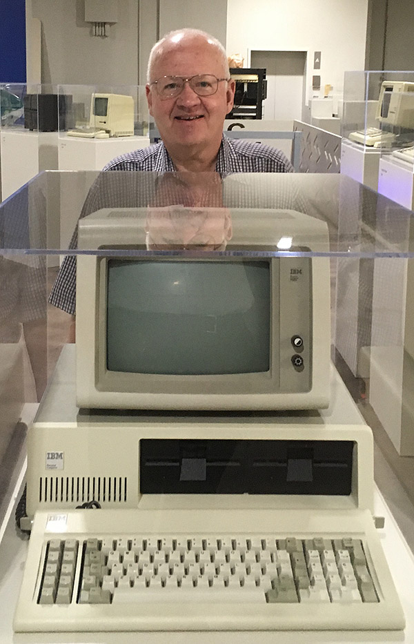
Computer museum:
Doug and I went to the
Computer Museum of America, on the north side of Atlanta,
and enjoyed meeting the founder, Lonnie Mims, and his wife Karin.
Besides the definitive collection of Cray supercomputers, they also have
everything from punched-card equipment to early micros (including an Apple I
and an Altair) and PDP-8's. Here you see me with an old friend, a 1982 IBM PC:
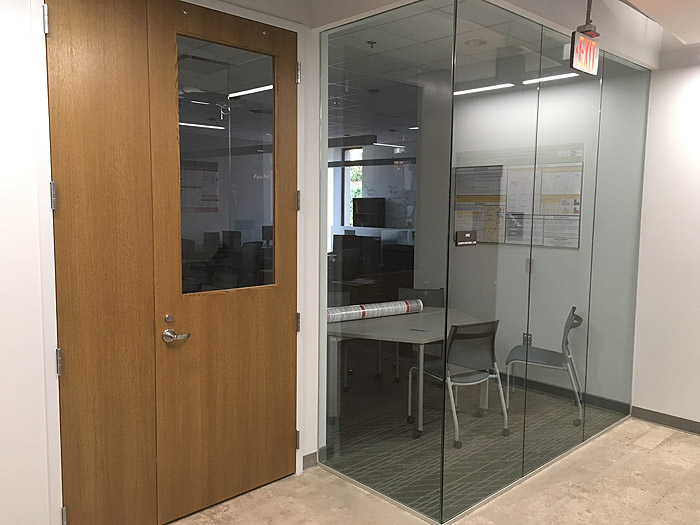
Where my office used to be:
It's unrecognizable. The basement of Boyd GSRC was remodeled beyond recognition
to make new labs for our College of Engineering. This lab (which is apparently not
yet in use) is where the AI Institute used to be. I don't think this picture
actually shows my office; you would get to it by going straight through the
wooden door and forward to the back wall. I must revisit it when it's open.
Teeth: Really attentive readers who recall that a couple of teeth
left me a couple of years ago
will be relieved to know that they've been replaced by bridgework, actually
involving original sculpture — I never had full-size teeth in those
positions until now. My lower teeth have also been strengthened, and gaps have
been filled in. As a result, I can finally bite a cookie like this —
something I actually never did before, at least not quite as neatly.

Permanent link to this entry

|
2019
September
30
|
Some co-authored astrophotos
My old friend Doug Downing spent a week in Athens and joined me for some
astrophotography. He brought his Canon XSi (450D) (not H-alpha modified)
and we used my Sigma 105/2.8 DG EX lens at f/4 and my AVX mount, at my
home on the outskirts of Athens, Georgia, where the Milky Way is barely
visible to a trained eye.
And we got results. I present these pictures as examples of what can be done
even though the site and even the weather were not first-rate (the sky was
a bit hazy).

Here's the Double Cluster in Perseus and, by good luck, at the top left, also the
Heart Nebula (IC 1805), which I didn't expect to show up.
Stack of ten 2-minute exposures at ISO 800, calibrated in the usual way with
darks, flats, and flat darks.
Permanent link to this entry
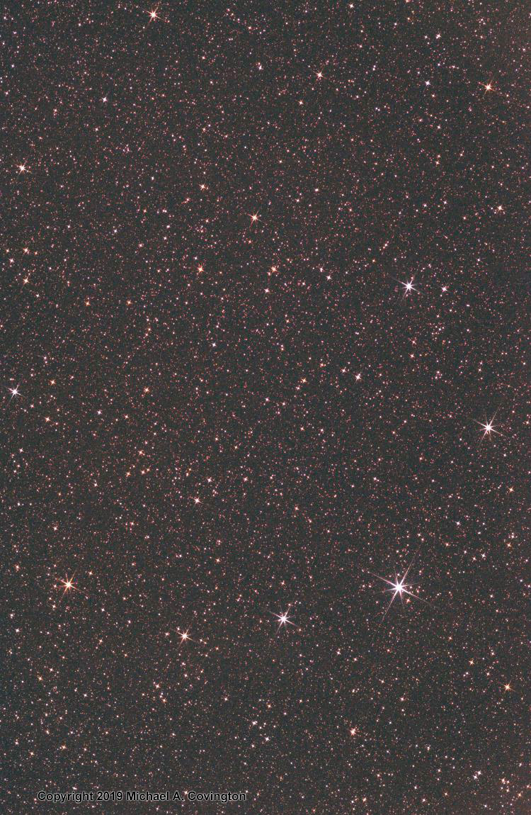
Sagitta and M27

Sagitta, the Arrow (not to be confused with Sagittarius, the Archer) is a small
constellation that looks just like an arrow; you see it in the bottom of this
picture. It comprises a pair of stars for the tail of the arrow (at the bottom
right) and two more stars and a star cluster along the shaft, pointing toward
the left and somewhat above horizontal. Above it is a nondescript bunch of stars called Vulpecula, the Fox, which looks
nothing like a fox as far as I can see.
The bright, compact star cluster in Sagitta, looking like a fat star,
is Messier 71 (M71), now classified as a globular cluster, although that
was uncertain for a long time.
Near the left edge, about 2/3 of the way from bottom to top, is the Dumbbell Nebula (M27),
a bright cloud of gas ejected by a collapsing star.
All of this is in the middle of the summer Milky Way, and you can see clouds
of stars and clouds of dark nebulosity (dust) blocking their light.
Stack of 10 2-minute exposures, same equipment and technique as above.
Permanent link to this entry
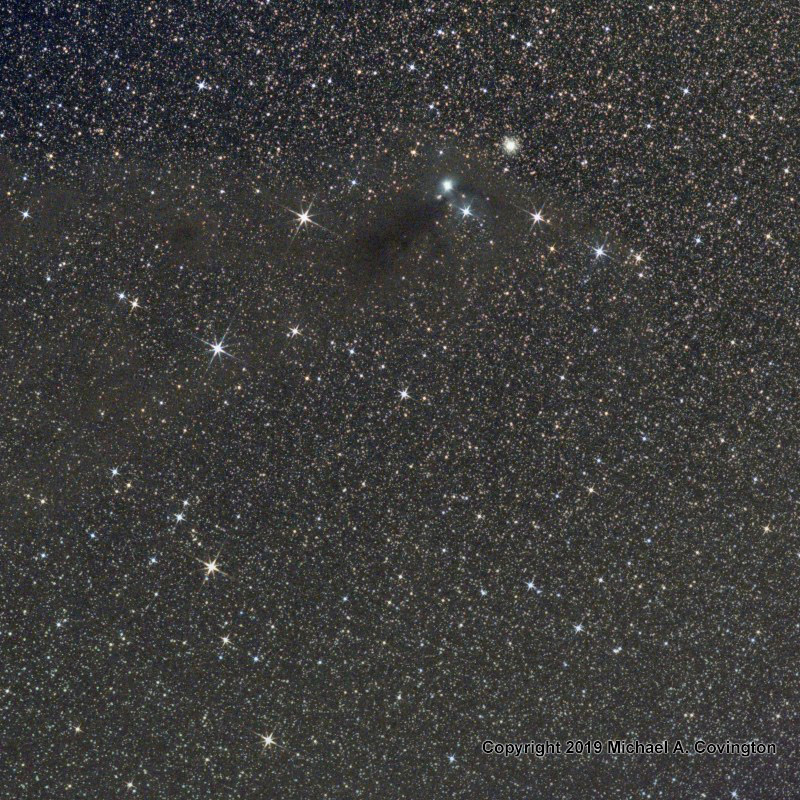
Scutum and M11
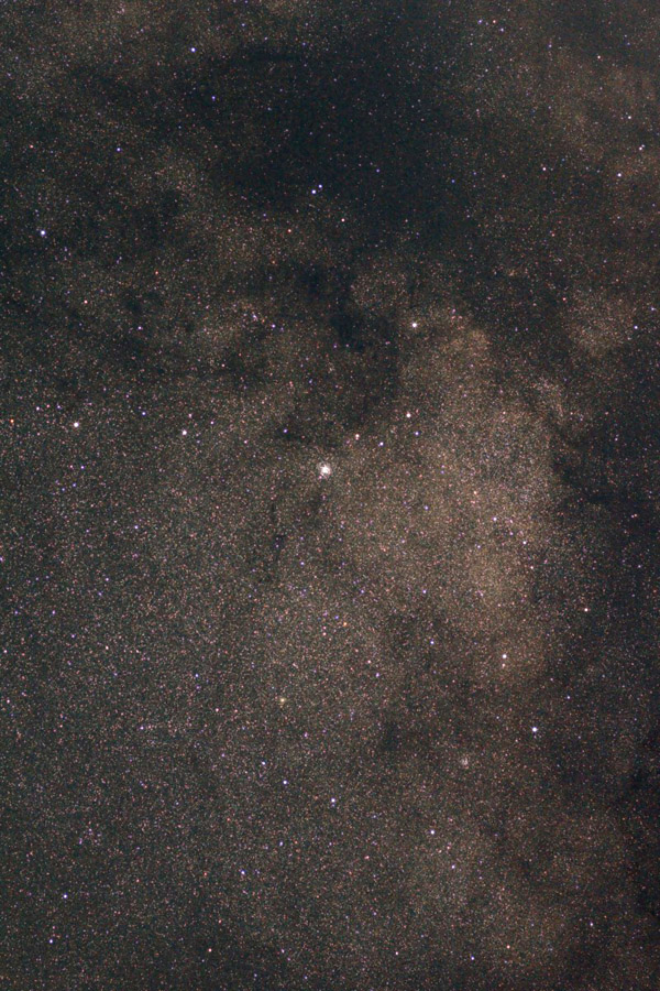
A particularly bright patch of the Milky Way is the Scutum star cloud, which you
see here. The stars in front of it constitute the constellation Scutum, the Shield.
The most conspicuous object near the center is the star cluster M11, a fine sight
in binoculars. Look at the tracery of star clouds and dark nebulosity in the upper
half of the picture.
Same equipment and technique as above, stack of only 8 exposures because a tree was
getting in the way.
Permanent link to this entry
North America Nebula

Musicians have theme songs and I have the North America Nebula; I never tire of
photographing it. This is a stack of ten exposures with the same equipment and
technique as the pictures above; we were delighted that Doug's camera, which lacks
H-alpha modification, picked it up so well.
Permanent link to this entry
|
2019
September
27
|
The spectrum of Vega
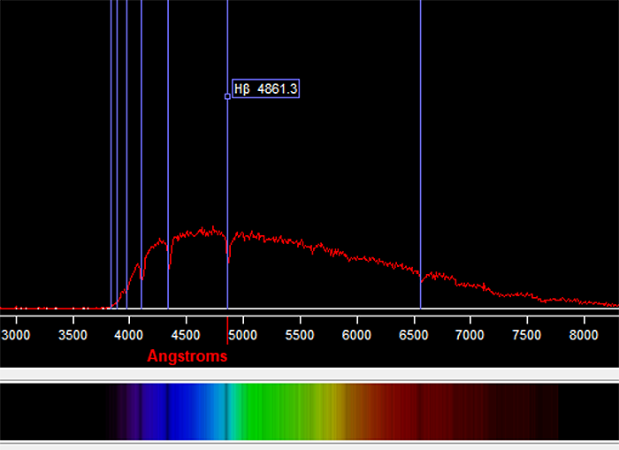
This is my spectrogram of Vega (see below) as analyzed by the software package
Rspec from Field Tested Systems, who
kindly supplied both the diffraction grating that I used to take the image
and the software that I used to analyze it.
It is flipped left to right compared to what I posted yesterday (below).
Vega is a bright white star, appreciably hotter than the sun, and it is of spectral type A,
meaning the absorption lines of hydrogen are very prominent.
In the diagram, the spectrum itself is plotted as a graph; the hydrogen lines are
marked in blue, and one is labeled; and below it you see a computer simulation of how
the spectrum would look if it were wider and photographed in color.
(The colors, i.e., wavelengths, of all parts of it are known, so synthesizing
the color image is straightforward.)
Nontechnical explanation: If you're not a scientist, what I just said may have
gone right past you. Let me explain a bit more fully.
You've seen how sunlight is spread out into a spectrum by a prism or by the water
droplets in a rainbow. Each of those actually produces a rather blurry spectrum.
If adjacent wavelengths are distinguished more sharply, as in this instrument, it turns
out that the spectrum contains dark lines, specific wavelengths at which the
light is dimmer. That is true of sunlight and the light of all stars. Some stars
also have emission lines, where the light is brighter.
The dark lines reveal what chemical elements are present in the outer atmosphere
of the star. In this case, we see a lot of hydrogen. The absorption of light at
those wavelengths by hydrogen can be replicated in the laboratory. That is how we
know chemistry is the same on earth as in the stars, and how we find out what the
stars are made of.
Permanent link to this entry
|
2019
September
26
|
My first spectrogram
My old friend Doug Downing is here for a visit, and we're trying out a
Star Analyser 100
and software kindly provided
by Field Tested Systems.
(The grating is made by PHEL in
Britain and marketed in the US by Field Tested Systems; the
software comes from Field Tested Systems
themselves.)
This is a diffraction grating ("blazed" so that most of the light goes into one of the many spectra)
that can be mounted in front of an astrocamera.
I used it on my ASI120MM-S (with 65-mm f/6.5 refractor telescope) and got
this 20-millisecond exposure of Vega:

The dark patches in the long streak indicate what chemical elements are present in the star.
Tomorrow we'll try out the software for analyzing it.
Spectroscopy is what revealed the chemical composition of the stars — and, perhaps
even more importantly, revealed that chemistry as we know it applies to places other than the earth.
Melody has just read The
Glass Universe: How the Ladies of Harvard Observatory Took the
Measure of the Stars and was excited to see spectroscopy actually being done, in our driveway.
This is an astronomical pursuit that doesn't require dark country skies. I figure that with exposures
up to 10 seconds, I can get good spectra of stars down to 6th magnitude; with autoguiding I can go
even deeper. The grating and software can be used with DSLRs too.
Permanent link to this entry
|
2019
September
23
|
"Capacitance multiplier" (buffered filter capacitor)
And yet another thing gleaned from EEVBLOG, which I'm noting here to come back to
(and to get practice drawing it with KiCAD).
In Episode 1116
Dave points out that a buffered filter capacitor (or "capacitance multiplier") is much
better at eliminating ripple than a voltage regulator chip.
Worth knowing if you need clean DC for an audio amplifier or the like.
I am particularly intrigued by the MOSFET version, which I had not seen before.
The dropout voltage is about 1.2 for the Darlington, or the turn-on voltage of the MOSFET,
whatever it might be (2 to 4 volts I'd expect).
Dave further points out that this is not really a "capacitance multiplier" —
it does not change the RC time constant or the frequency response, as a genuinely
larger capacitance would. It's a capacitor with a load buffer. It has no good name.
I propose to call it a buffered filter capacitor.
Permanent link to this entry
|
2019
September
21
|
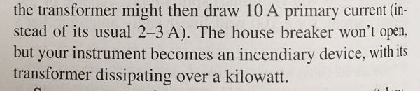
Avoiding a transformer tragedy
Another gleaning from EEVBLOG — an alarming one.
Dave accidentally
plugged a 120-volt soldering station into 240 volts
(the Australian line voltage) and what happened?
You might guess that either (1) a fuse blew, or (2) the
transformer burned out and stopped conducting.
No; neither one. Instead, the insulation inside the
transformer burned off, turning it into an enormous short circuit
that kept giving off heat
and would have started a fire if Dave hadn't seen what was happening.
It brought to mind this memorable passage
in The Art of Electronics:
Dave found a fuse and a Polyswitch on the output of the transformer,
but nothing protecting the input.
And although the mistake was Dave's, there were actually some further bad decisions
on Weller's part. The power cord was interchangeable (just like a PC) — not a
good idea if the voltage isn't changeable. And the voltage wasn't marked near where
the cord attaches; it was only marked on a label on the bottom of the device.
Dave wrote to Weller, and they offered him a replacement unit (wired for 240 V)
but made no acknowledgment or mention of this design flaw (not even to argue
that it's not a flaw). So he came away unimpressed, and now he recommends
Hakko and Pace soldering stations.
Basic safety rule: Always put a fuse upstream from a power transformer
unless the transformer is self-fusing (designed to burn out cleanly when overloaded).
I normally add fuses when updating older equipment
(example here and here).
I added one to my Weller EC2000, which is an older model of the
device Dave had his accident with (see below). Mine isn't likely to be plugged into 240 V,
but it could be hit by lightning, or a surge, or even suffer damage due to aging.
Note added 2022:
Discussion continues as to whether this was actually bad engineering. Maybe the
transformer was self-fusing, and this was a freak instance of it failing to
self-fuse. His accident was with the North American version of the WE1010, not sold
outside North America, and plugging it into a 240-volt line was not
foreseeable as a common accident. See also the note in the entry below.
Permanent link to this entry
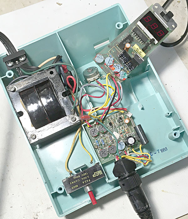
Weller EC2000 safety modification
I opened up my Weller EC2000 to add a fuse, to prevent the disaster described above.
The fuse goes between the black ("hot") side of the power line and the power
switch. So I wired up a fuse holder between the line and the switch, like this,
and stuffed the fuse holder in the empty space behind and under the transformer.
But wait a minute...
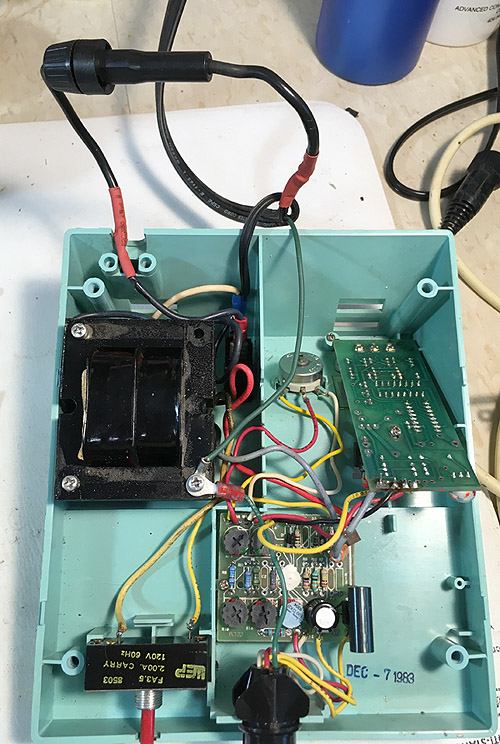
That wasn't the final solution. I continued to look at the diagrams and the
power cord and discovered that live and neutral were swapped!
Neutral is the ribbed side of the flat cord, and it went to the switch
(and hence also my fuse). That's wrong.
Note added 2022:
Discussion continues as to whether this was actually bad engineering. As noted above,
maybe the
transformer was self-fusing, and this was a freak instance of it failing to
self-fuse. Also, Weller is now a German company, and
in Germany
it is unpredictable which wire is live and which is neutral,
depending on the way the outlet is inserted into the socket,
so the swapping of live and neutral might not be significant to a German engineer
(though I still wish they observed the distinction to at least benefit users in
countries where it is maintained).
Basically, their design is what I would call double insulated plus ground,
with both live and neutral fully insulated from everything except the transformer
primary.
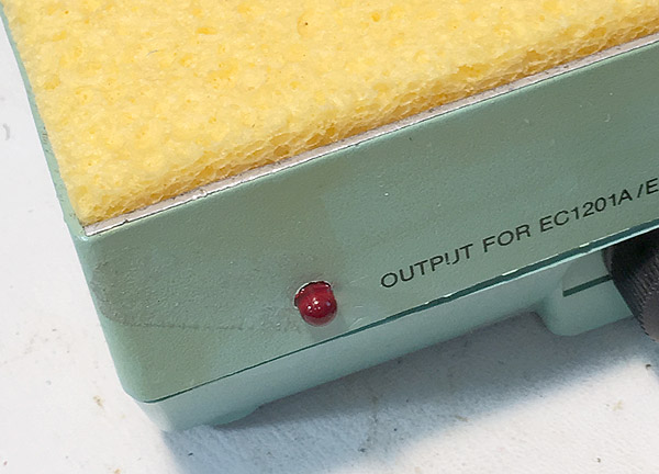
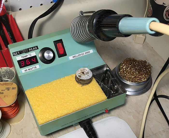
By the time the adventure was over, I had replaced the power cord and also
installed a status LED (described below). Here's what I ended up with:
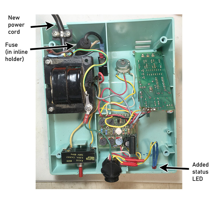
Read on...
Permanent link to this entry
Weller EC2000 status LED addition
I also decided to do another modification. I wanted to see how the
controller cycles the power to the iron. So I added an LED in parallel with the heating element.
Since it's powered from AC, the 1N4007 diode blocks reverse voltage; a common
1N4001 would do, but 1N4007 is what I keep on hand because it costs the same,
can handle higher voltages, and performs just like the 1N4001 at lower voltages.
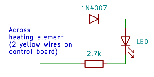
The LED is on when the iron is warming up, is off when it is cooling, and blinks at
about 1 Hz when it is maintaining a steady temperature.
Permanent link to this entry
|
2019
September
20
|
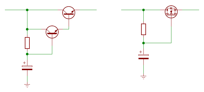
Two-transistor Zener clamp circuit
This is my "Daily Notebook," and today I'm making a note about something to experiment with later.
It's an electronic design idea from EEVBLOG #1157.
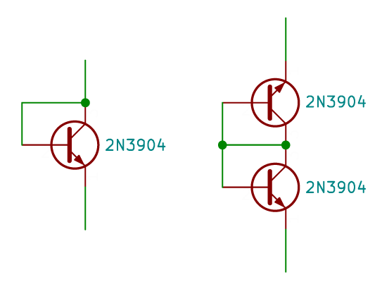
On the left you see a transistor connected as a diode.
This is a familiar configuration; it makes a good small-signal diode with a rather
low reverse breakdown voltage (somewhat more than VEBO in the
transistor's absolute maximum ratings, typically about 6 to 8 volts).
In breakdown mode it operates as an avalanche diode and makes a good white-noise source;
many, many, many years ago I used one, together with an LM386, to make a white-noise
generator to help Melody sleep in her noisy apartment.
More importantly, unlike other Zener or avalanche diodes, it has very low leakage at voltages
well below breakdown. EEVBLOG tells me the leakage is a few picoamperes at 4 volts.
The transistor data sheet tells me the capacitance is also low (a few pF), but I haven't
measured it.
Some say operating
a transistor in avalanche mode damages it; others deny it. It surely depends on the
amount of current sent through it. Discussion here.
Obviously I need to do some experiments.
On the right, you see two diode-connected transistors, connected back-to-back. This makes a bidirectional clamp
like two Zeners back-to-back, but with much lower leakage.
This circuit is, we are told, used to protect the inputs of Fluke multimeters
(and now, also, the EEVBLOG multimeter, which is why we're hearing about it).
Because of the low capacitance, I think it also has a future for protecting the
antenna input of a shortwave radio.
I'll return to this.
Permanent link to this entry
Hiding pin numbers in KiCAD
The alert reader may note that my circuit diagram was drawn with
KiCAD
rather than Visio.
I'm learning KiCAD because it is the emerging standard, a freeware CAD package
that is doing for electronics what LaTeX did for typesetting.
Crucially, it helps you turn your schematic into a printed circuit board,
and now that custom printed circuit board manufacturing
costs only a few dollars, I want to start building
things that way. (Two well-respected makers with very competitive prices
are JLCPCB and WellPCB.
I have not actually done business with either of those companies yet, but I hear good things about them.)
The seasoned KiCAD user will note that my transistors don't have pin numbers.
For clarity, I hid them.
How did I do that? By going to Preferences, Preferences (yes, same word twice in the menus)
and making the pin numbers white.
(For this to show up, I then had to right-click on an empty area of the
drawing and choose Redraw View.)
After I finished this diagram, I set the color back to
(132,0,0).
Permanent link to this entry
Exporting KiCAD schematics to JPEG, PNG, etc.
How did that KiCAD schematic get onto this web page? I'll tell you my trick.
I "printed" it to PDF, then imported the PDF into Photoshop. I could equally well have
displayed the PDF on the screen at the desired size and copied it with Windows' snip tool.
Permanent link to this entry
|
2019
September
16
|
Household archeology with an ultrasonic cleaner
For my birthday, Melody surprised me by giving me an
ultrasonic cleaner,
and, looking for something to try it on, I remembered that in the
utility room, we have an old cake tin full of grungy nuts and bolts,
dating from the mid-1960s and little changed for the past forty years.
So I grabbed a handful of things from it and cleaned them.
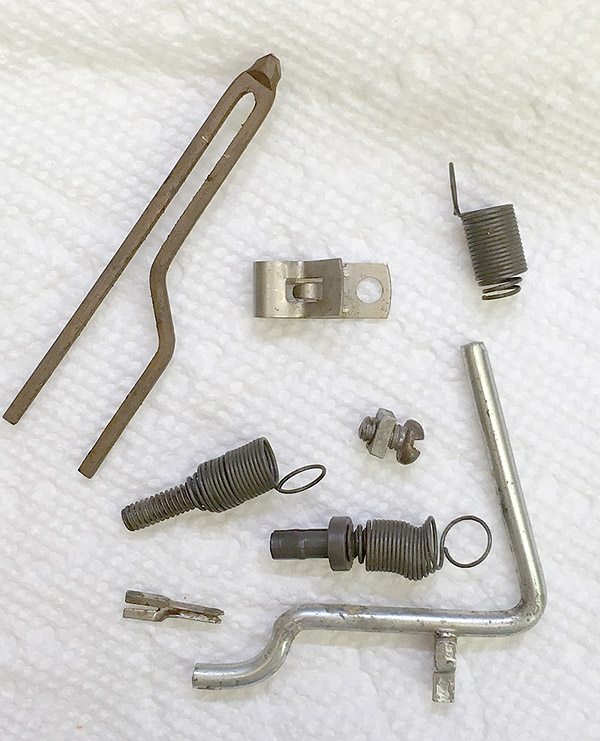
Everything in that handful of hardware brought back memories, but here are the most interesting
items. Here you see a tip from my father's Weller soldering iron (1964),
a Fahnestock clip from the crystal radio I built in the spring of 1966,
three spring connectors from my Knight 100-in-1 electronics lab (Christmas 1964),
a bolt and square nut from a Gilbert Erector Set that might be as old as 1960,
a pegboard hook from my father's workshop set up in 1964, and a Vector "flea clip"
(perfboard terminal) from about 1968. Melody has suggested putting them in a
shadow box for display...
...except for the pegboard hook. It's the good kind, with a rectangular prong that
grips the hole in the pegboard. I'm going to use that. All together, five
of them turned up and were cleaned. The rest of my father's 1964 pegboard hooks
are already in use on my pegboard (and have been since I moved into this house
in 1985). They are the only part of his workshop that is still in use.
Permanent link to this entry
|
2019
September
12
|
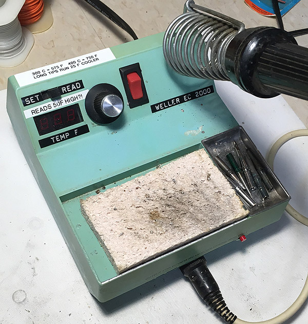
Weller EC2000 Celsius (centigrade) conversion
The other day, by using a thermocouple probe, I found out that my old, battle-weary
Weller EC2000 soldering station was reading 50 degrees F higher than the temperature
it was actually delivering. That is no doubt why several kinds of solder seemed so
finicky. Tonight I decided to calibrate it, and, while I was at it, switch it over
to Celsius (centigrade). That was done by turning adjustments, not flipping a switch.
Below are some pictures of the proceedings.
I bought this soldering station after someone else scrapped it around 1990,
and it had already lost its nameplate.
Tonight I cleaned it up a bit and even found an authentic Weller sponge
of comparable age.
A couple of warnings about measuring the temperature of a soldering iron with
thermocouples:
(1) A good measurement is hard to get. Put a droplet of solder on the tip of the
iron, and measure that. The highest reading you get, at a moment of particularly
good contact, is the correct one.
Let me underscore this.
A good reading is hard to get. As an alternative, you might test against the
melting point of SnCu solder, which is 227 C (admittedly rather below the range
at which you want the best calibration). I haven't done it, but it might be better to
test against pure lead
(supplied as a laboratory chemical),
which melts at 328 C, right in the middle of the temperature range of
most interest. Lead fishing sinkers may be pure enough.
(2) Not all thermocouples are rated for use above 250 C, even if they came with a meter
that will read much higher. I ruined one thermocouple (it failed open-circuit) and am going to
order a batch (5 for $14 on Amazon). Because of the fundamental physics of it,
thermocouples are accurate if they work at all.
The calibration process involved only the display board, not the control board.
Details are in
the instructions, which you can see by clicking here.
(I can't remember where I found them on the Web, but I thank my benefactor, whoever he or
she may be.)
The steps were basically the following:
(a) Short test point 2 to ground (the black wire) and set the Offset potentiometer
on the display board
make the display show -18 (if you're calibrating in C) or 000 (if you're calibrating in F).
(b) Remove the short, and read the voltage on test point 2, in millivolts.
Adjust the Gain potentiometer on the display board so that that's what the display shows (for Fahrenheit)
or so that the display is 18 millivolts lower (for Celsius). For example, if
the voltage is 500 mV, the display should show 500 (for F) or 482 (if you're going
to calibrate in C).
(c) Set the SET/READ switch to READ, let the iron stabilize for several minutes, and
carefully measure its temperature. If this isn't fairly near 700 F (360 C), adjust the
temperature setting (using the big knob on the control panel)
and try again. You want the iron at normal soldering temperature, but you don't have
to hit a particular temperature exactly.
(d) Adjust the Read potentiometer on the display board so that the display shows the actual temperature of
the iron (C or F, your choice).
(e) Set the SET/READ switch to SET and adjust the Set potentiometer on the display board
so that the same temperature is displayed (again, C or F, your choice).
It is very easy to bump these adjustments when putting the case back together, and I did,
so I had to open it up and adjust it again. (And again!)
It is my long-standing experience that if you have ever calibrated a piece of test equipment,
you will never trust it again. Certainly, this 36-year-old soldering station is rather delicate.
I'm not going to let the numbers on the display overrule my "feel" for whether the iron
is too hot or too cool at any particular time.
Permanent link to this entry
|
2019
September
11

|
Repair or throw away?
Rather than say shallow things about our "throwaway culture" I want to share an example of why it is so easy for a stereo, TV, etc., to be beyond economic repair.
In EEVBLOG 378,
Dave, a very skilled engineer and technician, finds a non-working Yamaha stereo receiver and tries to fix it.
Yamaha designed it to be fixed. It has a lot of information printed on the circuit boards. Everything is easy to get to. There are abundant test points.
Dave isolates the problem to the standby power-on circuit, and then explores... and tests... and consults the service manual on line... and after more than an hour of real time (40 minutes in the video), gives up.
(I have had similar experiences many times.)
There's a happy ending, because someone sees the video, gives him more information, and in
EEVBLOG 379 he fixes it. I haven't watched that one yet.
[It turned out to be a capacitor that was not at all failure-prone — seemingly one of
the most reliable parts in the whole amplifier — but Yamaha had gotten a bad batch of them,
and technicians who regularly serviced Yamahas knew about it. What's more, the capacitor was in one of
the strangest power supply circuits anyone has ever seen, built around a 4013 CMOS flip-flop.]
But the point is, it took a really good technician more than an hour's time (maybe worth $200 with overhead) to even make a good start. That's why people buy a new amplifier instead.
And the high cost of an hour of the technician's time is real.
This isn't 1950 and a technician can't live on $10 an hour.
It actually takes more expertise to repair consumer electronics than
desktop computers or industrial electronics, and there's plenty of market for
technicians' skills doing those things.
It's not that they don't respect delicately made things. It's that the cost of building one, by robots, is FAR lower than the cost of troubleshooting inside one that is already built.
I add that in a Yamaha shop, they would start with the service manual, as well as experience with the same or similar models, and would get it in less time. This one might take a Yamaha technician half an hour. But that is still a fair bit of time, with overhead.
Also, I highly approve of trying to fix things. Often, they're easy. When encountering discarded equipment I always like to check whether it's one of the 30% or so that are really easy to diagnose and fix. If so, free equipment!
Note about soldering in the 21st Century:
It came to my attention yesterday that I have two multimeters with thermocouple probes
that can measure the temperature of a soldering iron.
I had never used them.
They agree that my Weller soldering station is reading 50 degrees (F) higher than
the temperature it is actually delivering. That explains a lot
(no German pun intended).
Upcoming adventure: Recalibrating it, and maybe even making it read in Celsius while I'm at it.
Permanent link to this entry
|
2019
September
9
|
Soldering in the Mid-21st Century, part 2
See also part 1.
These are some further notes from online research
and my own experiments. I have continued to add notes.
There are two ways to solder, and they are often confused.
(1) If both objects are already freshly coated with the same kind of solder
you are already using, then all you have to do is add molten solder to
join them.
This is a good way to solder as quickly as possible, with
good reliabilty, even in awkward situations. Pre-tin both objects (which
requires flux; see below), and then, to join them,
simply apply some molten solder to them from the tip of the iron.
The iron only needs to be hot enough to melt solder (250 C will do).
(2) If the objects are not coated with solder,
or have been exposed to the air for some time,
flux plays a crucial role. Solder alone will not join them.
The flux in the core of the solder is normally enough, but you can add flux
if you want to.
The iron must be hot enough to activate and then burn off the flux,
not just melt the solder (310 C minimum, 350 C typical).
And the flux must get where it's needed. Always heat the objects
and then apply solder to the objects, not to the iron. If you do the latter,
the flux will burn off before it gets to the metal that it is supposed to clean. Although some wet
solder on the tip of the iron helps transfer heat, it does not make connections.
For that, you must apply solder, with flux in it, directly to the objects
being connected.
|
Lead-free: I continued using Kester K100LD SnCu solder last night
and got excellent results. The secret is to allow extra time for heating,
and feed solder slowly. The people who advocate small-diameter solder,
so you can't feed too much of it at once, are on the right track. The right
size is smaller than you think.
Looking at online forums I find a growing consensus that K100LD gets it right
whereas earlier lead-free solder was much harder to work with.
It's not only the alloy, but also the larger amount of flux.
Which means you need a fume extractor (mine is made from a PC fan).
One fact that Kester let slip is that other manufacturers' SnCu solder also
contains small amounts of other metals as additives but they don't say
what they are. That's why K100LD faces serious competition from
other brands of "99C" SnCu solder. And "Sn100C," a Japanese alloy, is reportedly
even more similar to K100D.
The high temperature is not just to melt the solder,
but also to activate the flux.
Recommended tip temperatures are 700 F (370 C) for lead-free
solder and for leaded solder with older types of flux;
600 F (315 C) for leaded solder with "no-clean" flux.
If the iron isn't heating the work well enough, you
probably need a wider or cleaner tip, not a higher temperature.
During the early days of surface-mount ICs, all of us stocked up on
tiny needle-like tips, but in fact we rarely need anything smaller
than 1 mm across.
Apart from overheating, an iron that is too hot burns up the flux before
it has done its work. A warning sign of this is brown or blackened flux left
behind.
Both Kester and Multicore tell us that removing ordinary rosin flux is optional
if it hasn't browned or blackened. They say it won't darken further or become
conductive. This is especially the case with "no-clean" flux, which is particularly
light-colored. Water-soluble organic flux, however, must be removed. Flux removal is
done with rubbing alcohol and an old toothbrush, with a water rinse.
Beware the wet sponge.
A wet cellulose sponge is great for cleaning the tip of the iron,
but it causes thermal shock
and lowers the temperature of a regulated iron
for as much as half a minute afterward.
Back in the days of unregulated irons, the iron was always too hot
(maybe 850 F) and a wipe with the wet sponge not only cleaned it but
got it down to a good working temperature, so we used the sponge
frequently. Nowadays a ball of brass wool is much better for cleaning
the tip, but you should still have the sponge available because it's
sometimes needed.
A Kester engineer further cautions that the sponge should be wet with
distilled water, since ordinary water contains some salt, which impairs
long-term reliability.
The point is, with an iron set to 750 F, I was fairly often soldering at 600 to 700 F
because of having used the sponge immediately beforehand.
Mixing leaded and lead-free: If you add lead-free solder to an
existing leaded solder joint, the two alloys may not mix well, and if
they do, the mixture will be far from eutectic — it will go through
a semisolid phase rather than hardening rapidly. But it's OK to repair
a joint of one kind with solder of the other kind if you remove most
of the solder. A thin coating, making only a few percent of the final
mixture, will do no harm.
Likewise, you do not have to keep separate soldering-iron tips for leaded
and lead-free unless your work has to be certified free of lead.
Just tin the tip with the kind you are going to use, clean it in the ball
of brass wool, and tin it again.
Do not clean the solder off the tip before storing it. Leave solder on it,
and clean it just before you use it again.
One last hint:
Cut the end of the solder before using it, especially if there was a ball
left on the end of it from last time. Cutting a tiny bit off helps
the flux get out.
When reading studies of solder alloy performance, note that tensile or
shear strength is not what you want. A solder joint that is somewhat
flexible is likely to hold up better under thermal cycling.
Broken solder joints on components that heat up (power transistors,
high-power ICs, anything on a heat sink) are a common cause of equipment
failures — work looking for the next time you troubleshoot a TV or stereo.
Finally, anyone researching lead-free solder is likely to come up with
this study from Britain's
National Physical Laboratory.
Looking at it closely, I am not sure it can be relied on — in fact, the authors
admit some problems with experimental technique.
The results seem to be chaotic, indicating that there might be large errors.
Afterthought: I don't know much about metallurgy, but it is apparently an area
of chemistry where things ought to be simple but there are still a lot of
mysteries. If I were a chemistry student, I would be attracted to it.
Permanent link to this entry
|
2019
September
7
|
Two planets
Although not quite used to my increased workload, I haven't stopped doing
astrophotography. Here are two planet pictures, not taken on the same night.
Each is a stack of the best 75% of thousands of video images taken through
my 8-inch telescope.

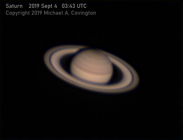
Jupiter and Saturn are in the part of the Solar System that the earth's north pole
is tilted away from. I'm tilted away from them too, because I live in the Northern
Hemisphere. So they don't rise very high in my sky, and I always have to look at
them through a lot of unsteady air (think about it — there's less air high
overhead you than at a low angle). Also, the earth is moving past them in its
orbit, so they will soon not be in our evening sky at all.
Permanent link to this entry
You know you're doing 21st-century electronics if...
Humor department... [Later additions in blue.]
You know you're doing 21st-century electronics if:
-
Five volts is "high voltage."
-
It is cheaper to add another microcontroller to your circuit than to add a capacitor.
-
Nanofarads. None of this 0.1 business.
-
Your prototypes look like stamp collections made of Adafruit breakout boards.
-
The IC number printed on the breakout board is bigger than the IC itself.
-
You have two full sets of soldering-iron tips, leaded and lead-free.
-
Nanofarads (again).
-
Some of your test instruments are so small that if you put them in your pocket, you lose them.
-
You need a nanoammeter.
-
One of the instruments lost in your pocket is a nanoammeter.
-
You no longer feel unpatriotic when you draw resistors as boxes rather than zigzags.
-
Brown is live, blue is neutral, and you learned this fact in North America.
-
"20 µF" does not imply "electrolytic."
Additions to the list are welcome.
The alert reader will already know that I'm modernizing my electronics workshop and my knowledge
of current practice. For about fifteen years, family and job obligations kept me away from
electronics as I only did software (my real profession). Now I'm determined to catch up, and the
biggest change I'm noticing is economic: Now the most modern way to do things is also the
cheapest. A lot of what's hot now existed in 2005 but was expensive. Not any more.
The other thing I've noticed is replacement of print media by the Web and video.
Really current information is distributed very informally through web sites and forums.
Particularly outstanding is David Jones' EEVBLOG
videos and forums. Some of the videos have had a million views. One of the most
entertaining is this tall tale,
which made its debut March 31, 2017, and was obviously released one day too early
because of time zone differences.
Where any kind of work with tools is involved, there's no substitute for watching people
and seeing how they actually do things. That's what EEVBLOG shows plenty of.
There are also the repair videos by
Louis Rossmann, who does repairs on Apple laptops that are seemingly impossible — and
rants about the way Apple treats customers.
In both Rossmann's videos and EEVBLOG, watch out for offensive language.
For that reason, I don't consider these videos suitable for audiences below college age.
Peppering one's speech with scatology is, in my opinion, a sign of inarticulateness
and disrespect.
Another thing about EEVBLOG that grates on me is Dave's vehement opposition to "religion"
and especially Christianity. I wouldn't expect this subject to come up repeatedly in
an electronics blog, but it does. He can be an atheist if he wants, but I wish he would show
some awareness that some very intelligent people are on the other side. Surely he doesn't
consider Lemaitre and Knuth to be fools — if he knows about them?
EEVBLOG vocabulary note:
You'll hear lots of Australian slang that is puzzling but not offensive.
"Come a gutser" is very obscure WWI slang for "fail."
I don't think it's offensive.
I'm not sure anyone knows what it really means.
The leading theory is that a "gutser" is a belly-flop, a badly
executed dive that hits you in the guts.
Addendum: There are many sources of electronics videos on the Web.
See for instance this excellent
soldering tutorial in a series called Beauty and the Bolt
(very suitable for pre-college student audiences, and good for encouraging women;
and it also covers crafts other than electronics).
Contextual Electronics is also very promising;
they sell online courses, but apparently they also have videos that can be viewed free on YouTube.
Permanent link to this entry
Soldering in the Mid-21st Century
Around 2004, some countries banned, and all countries started to discourage, the use
of lead solder in consumer electronics.
At the time, I got some SnAgCu (SAC) lead-free solder and didn't much like it.
Fast-forward to 2019, and we're no longer snagged on SnAgCu. Many companies and
technicians are switching to SnCu (99C), which is cheaper and looks much better when
it hardens. See the difference:
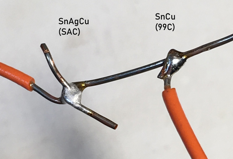
Note: It turned out that all of these were soldered at lower than
recommended temperature. See other entries (above) for further notes.
This is with Radio Shack brand SnCu solder whose exact composition I do not know.
But the key difference is, SnAgCu supposedly bonds better but looks worse;
SnCu looks better, and we can actually see whether it has bonded well.
That may make up for the slightly greater difficulty in getting a good bond.
That's not the end of the story. Lead-free solders are notoriously finicky, and
metallurgists have discovered that small amounts of impurities have been having large
effects. Leave it to Kester (the main American solder maker) to find out what impurities
help, and deliberately add them.
Kester K100LD
is SnCu with tiny amounts of nickel and bismuth added.
I hear nothing but good things about it. I'll have some in a day or so and will be
able to report on how well it works.
See Kester's technical reports here
and here.
Update: K100LD is probably the best lead-free solder I've tried.
The iron must be hot enough, and the solder must be fed to it slowly.
And that's still not the end of the story.
People are just now realizing that you need plenty of flux and we had been
trying to use far too little of it. Traditional lead-based solder is about 1% flux,
provided in the hollow core of the solder itself.
SnCu solder needs to be (and the one I linked to is) about 3% flux.
What's more, a new kind of flux is on the market, gelatinous and not strong-smelling.
I got some from Caig,
and it works well.
Louis Rossmann actually practices
immersion soldering —
he puts down a thick glob of flux, melts it, and solders right through it.
This makes solder stick only to metal, not to anything else, and he gets
neat results.
That's still not all. Multicore solder is back. I bought some in England in 1978,
found it very good to work with, and couldn't get it when I came back to the USA, even though it
had been marketed here earlier. Now Loctite has bought the brand, and you can get it again.
Marketing in the USA is spotty, but you can definitely get
the lead-based kind,
which I'd stock up on if I didn't have a lifetime supply of some Kester products.
They also offer some lead-free alloys, but I'm not fond of SAC; their SnCu (99C) is hard
to get; and among suppliers I find real confusion as to exactly which product they are supplying
and how many cores it has.
The goal of the multiple cores is of course to deliver plenty of flux.
Another tidbit I picked up is that I was probably using too small a soldering-iron tip.
Bigger tips deliver more heat.
And there's a new type of soldering iron
(example: Pace ADS200)
that gives much better temperature control because the sensor is in the tip.
My soldering station is a Weller EC2000 that someone else discarded about 25 years ago.
It works, but I'll probably upgrade some time before long.
There are two ways to use a temperature-controlled iron.
My own approach has always been "hot and quick" — set to a high temperature
(400 C) and solder quickly.
Many agree with me that it is easier to overheat things with an iron that's too cool
than one that's too hot, because the cool iron has to be held on them longer.
Of course, "hot and quick" is the natural approach for someone who learned using
unregulated irons half a century ago; all soldering irons were too hot then.
Today, however, there are situations where it's hard to avoid prolonged heating of parts.
When that is the case, the approach is to set the iron just barely hot enough to
melt solder (300 C or even 250 C) and work more slowly, knowing that most parts are
rated to survive an internal temperature of 260 C for 10 seconds or more.
Permanent link to this entry
The L in solder
Why do Americans pronounce solder as "sodder"?
It turns out that the answer is the same as why we pronounce salmon as "sammon."
The word was borrowed from French, in which al and ol had already turned into au and ou,
respectively,
in some contexts. It was soudur when we got it from French.
(Salmon, the fish, was saumon.)
Then someone noticed that the original Latin word had an L (solidare 'solidify' for
soldering; salmo for the fish) and put the L back in.
I'm not sure, but some evidence seems to indicate that in the case of solder this
re-Latinization took place in French as well as English, at least for a while
(the French today call solder soudure, so it didn't stick).
So in this case the Americans seem to be using the older pronunciation.
Permanent link to this entry
|
2019
September
1
|
A walk through Sagittarius

Despite my newly increased workload, I got to the Deerlick Astronomy Village
on August 28 to take advantage of a rare phenomenon — clear weather.
That's right, the clouds of August have finally cleared, and we had three clear
nights in a row, of which that was the first.
I took my Nikon D5500 (H-alpha modified), Sigma DG EX 105-mm f/2.8 lens,
and AVX mount, performing "all-star polar alignment"
with the lens and camera, then relying on PEC for smooth tracking.
It worked; I got excellent 4-minute exposures.
What you see here is a stack of six 4-minute exposures at f/4.
Top to bottom, going down the center of the picture, you see the star
cluster M21; the red-and-blue Trifid Nebula, which contains both red emission
nebulosity and blue reflection nebulosity; the big reddish Lagoon Nebula (M8);
a huge star cloud that is sometimes called "steam from the teapot" (look at
the shape of Sagittarius on a map to understand that); and the star Gamma Sagittarii.
There are also many streaks and patches of dark nebulosity (space dust that
blocks light from the stars), of which the most striking is the little dark
spot B86, right next to a star, just below the center of the picture.
Permanent link to this entry
A negative result
One of my ongoing projects is to look for low-surface-brightness nebulosity
like what I photographed back in April.
Some streaks on an earlier photograph made me wonder if there was any of this in
the constellation Corona Borealis, and having taken this picture, I can
answer: no, at least nothing nearly as bright as the IFN in Ursa Major.
This is a stack of ten 4-minute exposures. It was processed differently
from the others — lighter and redder — to bring out faint nebulosity,
of which there isn't any.
I continue to suspect, though, that there might be slight streaks of dark
nebulosity near the bottom of the picture.
I can't be sure; maybe it's random variation in the arrangement of stars.
Permanent link to this entry
The other Corona
Here is Corona Australis, the Southern Crown, shaped a lot like Corona Borealis
but oriented differently,
fainter, and from our latitude, only above the horizon a small amount of the time.
This is a stack of eight 4-minute exposures, and you can see that there's more
here than just stars. The northernmost (topmost) bright object is the globular
cluster NGC 6723. (Yes, you're seeing a globular cluster partly resolved with
an aperture of one inch. This lens is good!) To its lower left is a big
dark nebula, as well as a pair of stars embedded in reflection nebulosity
(surely the same material, just with stars illuminating it). I am told there
is a variable nebulosity here, and this is a field I'd like to photograph with
a larger instrument.
Permanent link to this entry
Rho Ophiuchi
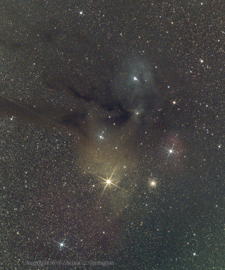
If you like mixed nebulae, here you see four kinds: emission (red), reflection (blue-white),
reflection with larger dust particles (yellowish), and dark. The yellowish nebula may actually
be the same material as the white, but reflecting light from a yellowish star (the "red" star
Antares; red stars are yellowish). I haven't delved deeply into the astrophysics of this
region. You also see a globular cluster extensively resolved (with one inch aperture) and,
as a bonus, a diffraction spike from Jupiter, which was outside the field.
Stack of six 4-minute exposures at f/4.
Permanent link to this entry
Astrophotography without astrophotography
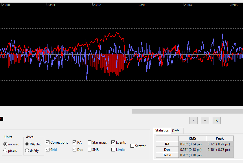
On Friday evening (Aug. 30) I set my telescope up for visual observing at home and also
conducted an autoguiding test. As you can see (if you're a connoisseur of PHD2 guiding
graphs), everything worked well except that excessive declination backlash led to a single
sawtooth-shaped event in the middle of this picture. I will probably adjust the CGEM worm
gear to reduce the backlash.
I wasn't photographing anything, just testing the mount, to rule out a possible mechanical
problem which, I am now convinced, was just a balancing issue, and which I couldn't investigate
further during the cloudy six weeks that ensued after I experienced it.
Permanent link to this entry
|
|
|
This is a private web page,
not hosted or sponsored by the University of Georgia.
Copyright 2019 Michael A. Covington.
Caching by search engines is permitted.
To go to the latest entry every day, bookmark
http://www.covingtoninnovations.com/michael/blog/Default.asp
and if you get the previous month, tell your browser to refresh.
Portrait at top of page by Sharon Covington.
This web site has never collected personal information
and is not affected by GDPR.
Some older pages that contain Google Ads may use cookies to manage the rotation of ads.
No personal information is collected or stored by Covington Innovations, and never has been.
This web site is based and served entirely in the United States.
In compliance with U.S. FTC guidelines,
I am glad to point out that unless explicitly
indicated, I do not receive substantial payments, free merchandise, or other remuneration
for reviewing or mentioning products on this web site.
Any remuneration valued at more than about $10 will always be mentioned here,
and in any case my writing about products and dealers is always truthful.
Reviewed
products are usually things I purchased for my own use, or occasionally items
lent to me briefly by manufacturers and described as such.
I am an Amazon Associate, and almost all of my links to Amazon.com pay me a commission
if you make a purchase. This of course does not determine which items I recommend, since
I can get a commission on anything they sell.
|
|